Coating Inspection and Inspection Equipment
Advanced Nondestructive Tests
Slide /
Introduction
This unit imparts a knowledge and understanding of:
- Magnifiers
- Microscopes
- pH meters
- Detection of moisture — indicators and tests
- Eddy current thickness gauges
- Advanced data collection methods
- Ultrasonic thickness gauges
Magnifiers
A magnifier is used to closely inspect a surface to examine for example, the surface profile, the presence of contamination, blistering and associated underfilm corrosion, rust, pinholes, and other surface or coating defects.
Magnifiers are available in a variety of sizes, types and magnifications. There are also illuminated ones that are useful in low light conditions.
N.B. Magnifiers are not used to evaluate surface cleanliness as per NACE/SSPC standards.
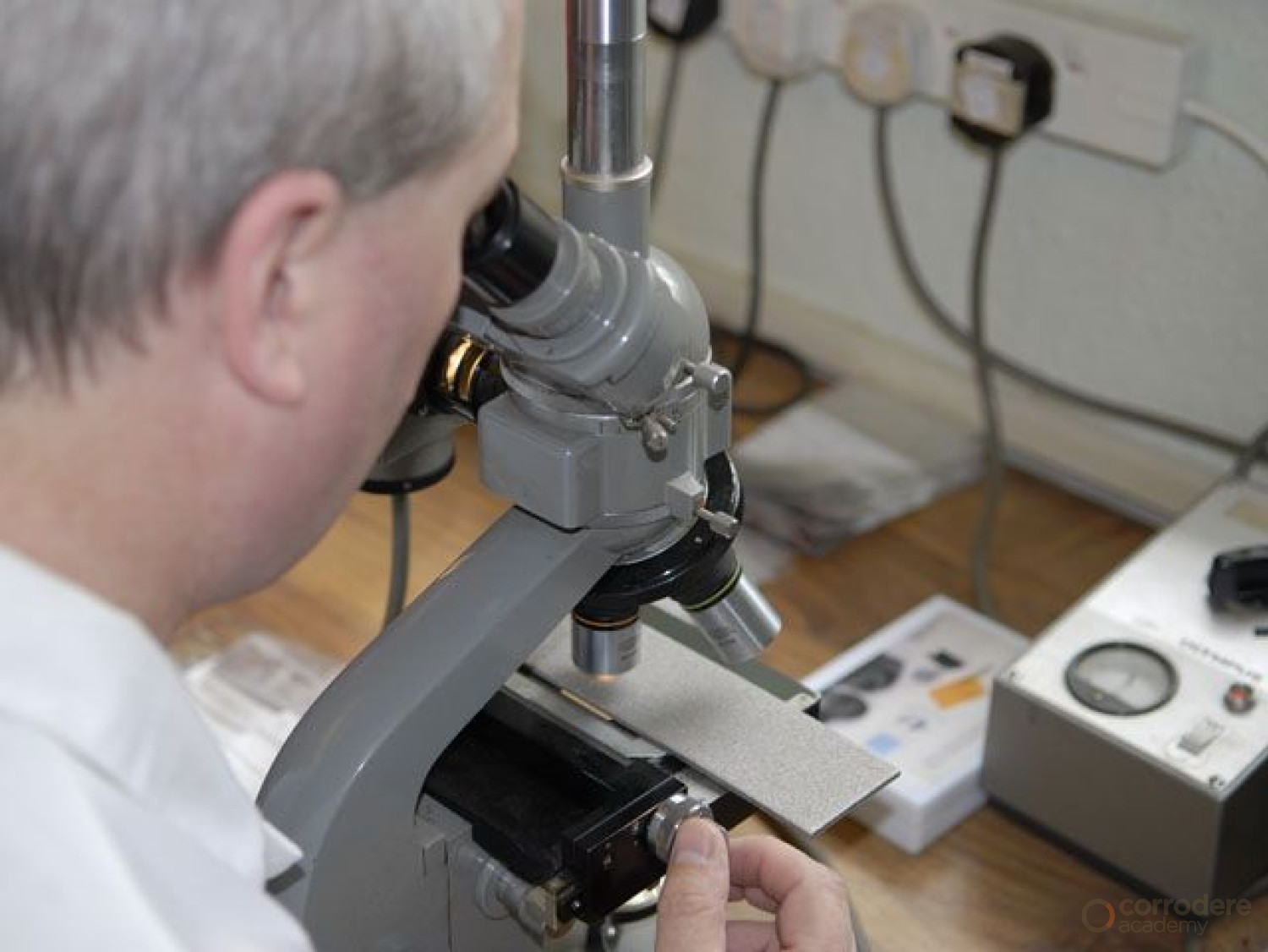
Microscopes
The common types of microscopes are:-
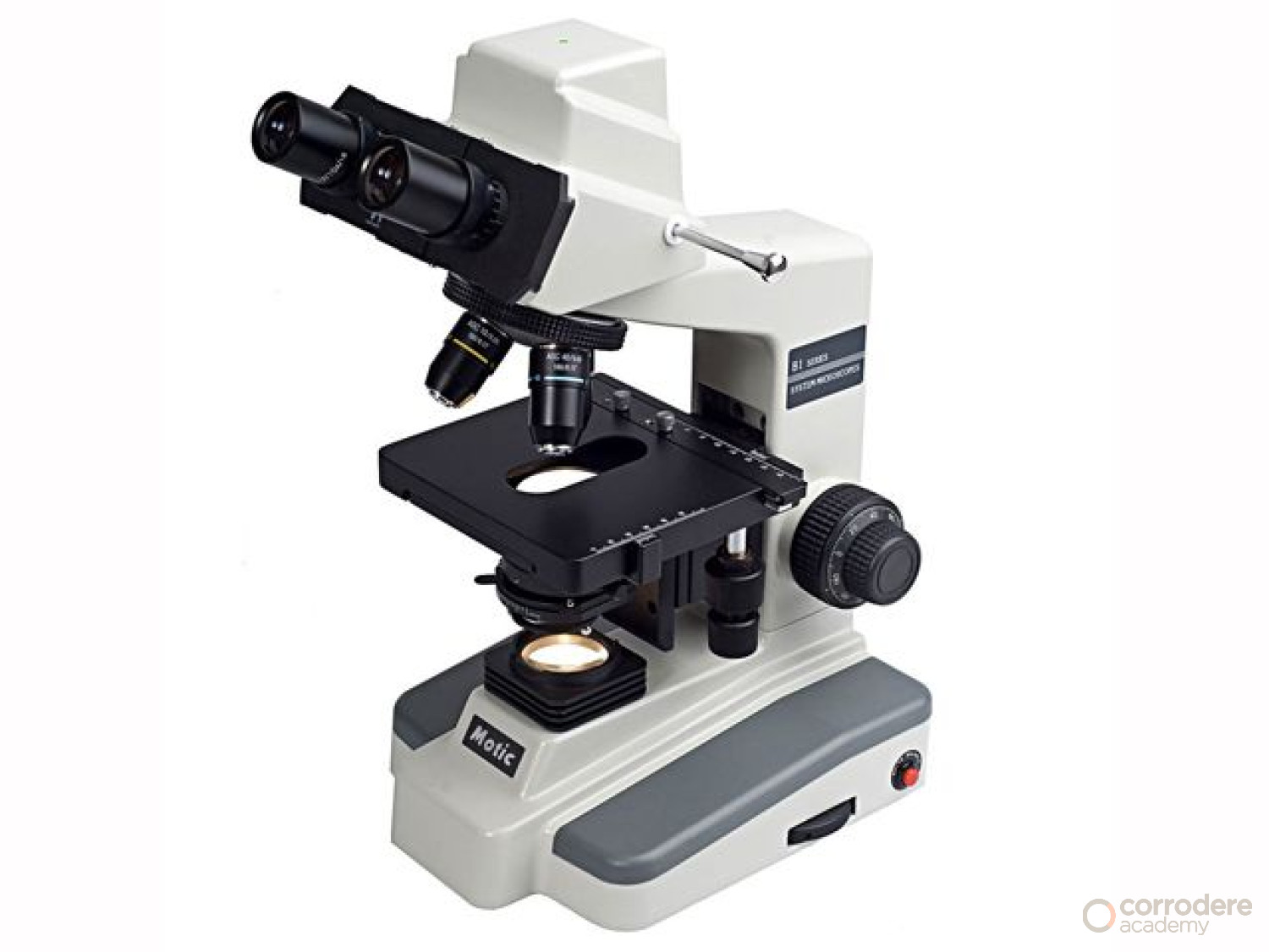
- Optical microscopes that use visible light and a system of lenses to magnify images.
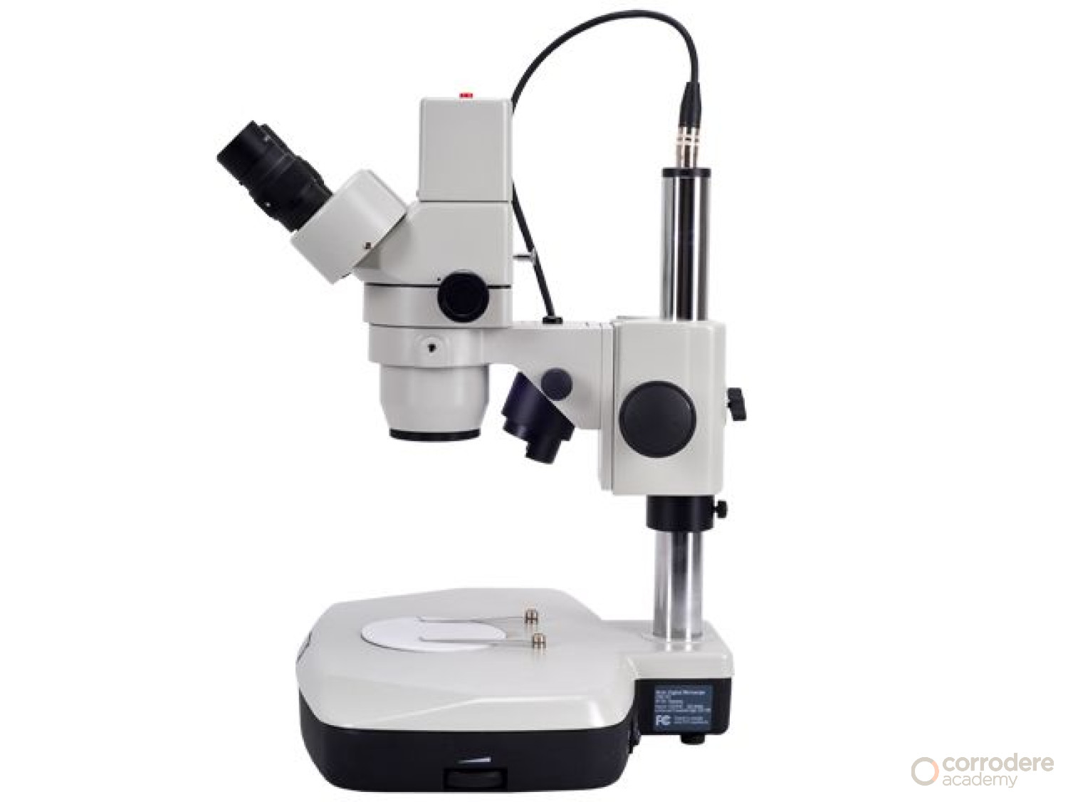
- Stereo microscopes that use visible light but with two separate optical paths with two eyepieces and two objectives each providing a slightly different viewing angle for the left and right eye producing a three-dimensional effect.
- Digital microscopes that use optics and a charge-coupled device (CCD) camera to output a digital image to a monitor.
Optical Microscopes
They range from simple microscopes with one magnifying glass to compound microscopes
with several lenses.
Portable microscopes for Use in the field are available with a built-in battery-operated light source.
The magnification range is generally from 20X to 300X and some are available with scales or graticules graduated in inches or millimeters to provide a means to measure for example dust size, the width of cracks etc.
In field use's the microscope is held against the surface, focused and viewed through the eyepiece.
A torch can be used if there is no built-in light source.
No calibration is required and the instrument magnification should be chosen to suit the conditions noting that at higher magnifications focussing is more difficult and the depth of field is reduced.
If a scale or graticule is included its accuracy can be checked by use of a known length or scale accuracy by measuring a known length or stage micrometer.
Stereo Microscope
Stereo microscopes are normally used in laboratories and are available with magnifications of up to 600X. However, they are generally used at magnifications of less than 100X due to the low depth of field at higher magnifications.
The focus and position of the subject through the eyepieces is adjusted using the course and fine adjustment controls and stage controls.
Lighting of the specimens is important and various light sources are available to achieve good quality images.
Digital Microscopes
With a digital microscope, the image is projected directly onto the CCD camera and viewed on a monitor.
Optics for the human eye are omitted completely in some instruments.
Digital microscopes generally have both an optical and a digital zoom with the image quality of the optical zoom being superior as the actual object is magnified rather than the digital method which interpolates the pixels and increases them based on calculations.
The magnification for a digital microscope is determined by how many times larger the sample is reproduced on the monitor; therefore, the magnification may depend on the size of the monitor.
Generally the greater the magnification, the lower the image quality.
Some instruments can produce in addition to still images, video and time-lapse sequences.
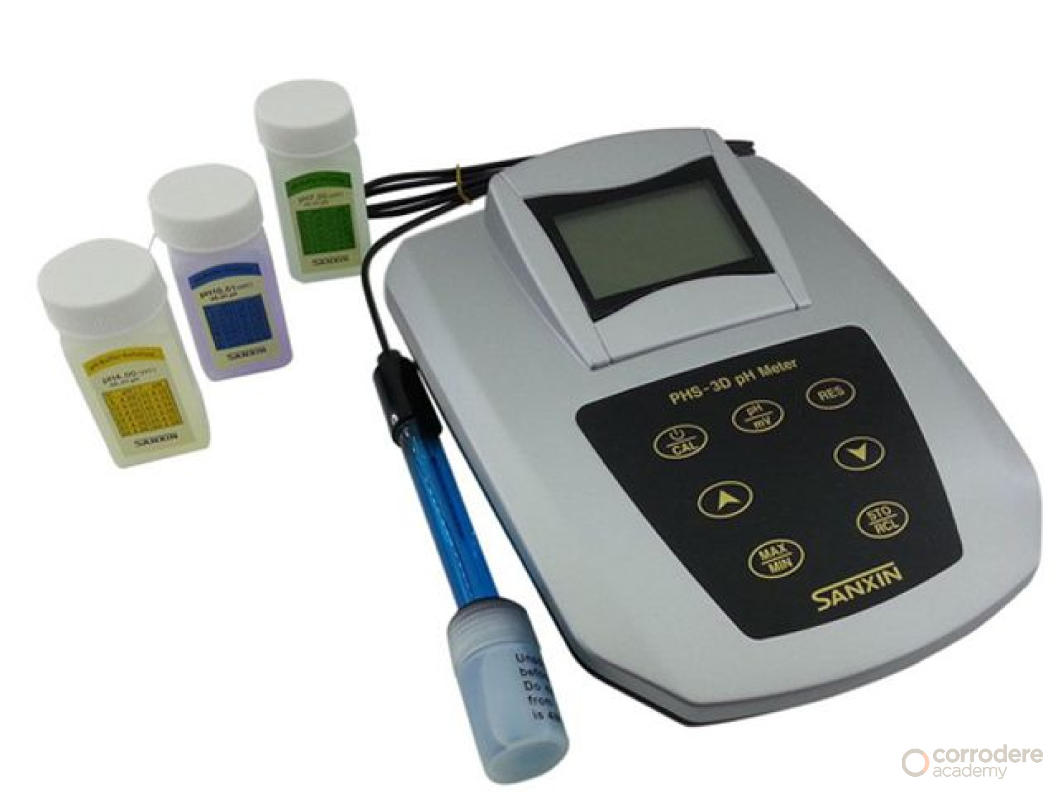
pH Meter
pH is a measure of the hydrogen ion concentration and an indication of the acidity or alkalinity of an aqueous solution. A pH of 7.0 is neutral, the pH range of 0.0 to 7.0 is acidic, and the range from 7.0 to 14.0 is alkaline.
The scale is logarithmic hence a pH of 3 is ten times more acidic than a pH of 4.
Both laboratory and field instruments are available.
They use the same principle of measurement with a glass electrode and a reference electrode often as a combined single probe.
As pH varies with temperature compensation is either built into the probe or tables are used.
Calibration is carried out using standard buffer solutions of known pH values at a specific temperature with pH 4 and pH 9 is frequently used.
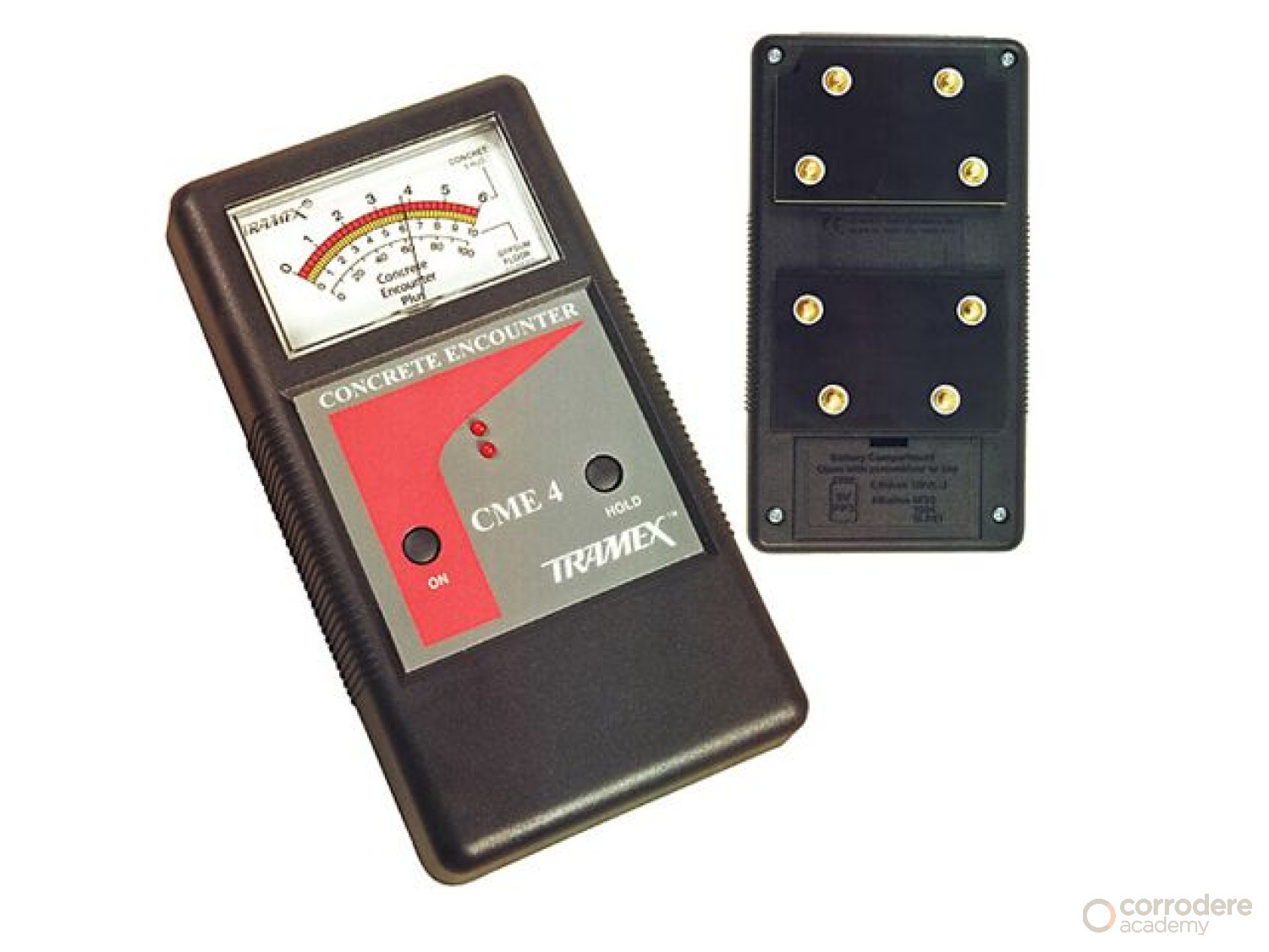
Moisture Meters
Coatings applied to substrates that are porous and absorb moisture can fail due to the moisture content.
Simply ensuring that the surface is dry is insufficient as the surface of the substrate is often the driest point due to evaporation and so the moisture content within the substrate needs to be measured.
A number of tests and instruments available to check for and/or measure the moisture content of substrates such as concrete, plaster and timber.
The type with sharp pins that are pushed into the substrate work on a conductivity principle whereas others are non-destructive and are simply placed in contact with the surface.
Some instruments have different scales depending on the substrate being tested and all should be regularly checked and calibrated using a known moisture content sample.
Eddy Current Thickness Gauges
These Instruments often called non-ferrous gauges, are used to measure the Dry Film Thickness (DFT) of non-conductive films applied to conductive substrates such as aluminum, copper, brass, and stainless steel.
They work by inducing an eddy current in the substrate using a high-frequency alternating current fed to the probe.
ASTM B 244, ASTM D 7091-05, and ISO 2360 are standards relevant to methods for the application and performance of DFT determinations using these gauges.
Eddy current instruments can give false readings on ferrous substrates and when measuring the DFT of a material such as an aluminum-pigmented coating over a substrate like copper.
Eddy Current Thickness Gauges continued Calibration
Use a plastic shim with a thickness value slightly higher than the expected maximum reading.
Check the minimum substrate thickness from the manual (Typically, a substrate should be a minimum of 70 mils thick).
Carry out calibration verification on the prepared, uncoated surface to take the profile into account.
Verify and adjust the gauge per the manufacturer’s instructions.
As a general rule, verification on smooth surfaces can be done using a shim with a thickness slightly above the expected maximum DFT.
Verification on a surface with a profile may require a two-point procedure using two shims, one with a thickness above the maximum expected DFT and
the second with a thickness below the expected DFT.
For maximum accuracy, the two-point verification should be used.
Eddy Current Thickness Gauges Continued Accuracy
The following factors may affect the accuracy of eddy-current gauge measurements:
- Magnetic and conductive properties of the substrate, particularly the low conductivity of some non-ferrous metal substrates.
- Substrate thickness. The minimum thickness can vary with different instruments.
- Edges. Generally, measurements will not be accurate when made closer than 1 in (25 mm) to an edge.
- Curved surfaces. If this type gauge is used to measure DFT on a curved surface, the probe should be held at right angles to the surface and, if possible, calibrated on a similar curved surface.
- The conductivity of coatings. E.g. Measurement of coatings, such as aluminium pigmented coatings.
The manufacturer's instructions should be closely followed.
Ultrasonic Thickness Gauges
This type of gauge utilises an ultrasonic pulse-echo technique to measure the thickness of coatings on non-metal substrates.
The instrument probe contains an ultrasonic transducer that sends a pulse through the coating (with the assistance of a couplant) which is reflected back from the substrate to the transducer.
It is converted into a high-frequency electrical signal and the echo waveform is digitized and analyzed to determine coating thickness.
If the reflection occurs at a different coating layer due to differing mechanical properties the individual layers of the system could be measured.
Typical tolerance is ±3% and ASTM 6132 covers the use of this type of equipment.
Ultrasonic Thickness Gauges (cont)
The gauges usually require no adjustment to the factory calibration settings but verification checks can be carried out with known reference standards.
The accuracy of an ultrasonic measurement is directly related to the sound velocity of the coating being measured hence they must be calibrated for the “speed of sound” in that particular material.
Errors can be caused by the operator inputting incorrect information to the gauge such as the wrong number of layers in the coating system.
They can also be caused by porosity and surface roughness that can give rise to irregular readings.
The manual for the gauge should be consulted at all times.
Summary
Within this training unit, we have looked at advanced non-destructive tests conducted on coated surfaces.
A lot of this work is for investigation purposes and therefore conducted in a laboratory which has special magnification equipment etc.
